SemiconductorMedium
Question
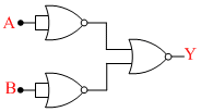
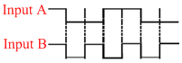
The logic circuit shown below has the input waveforms ′A′ and ′B′ as shown. Pick out the correct output waveform :-
Options
A.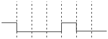
B.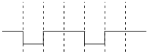
C.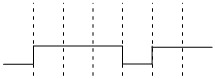
D.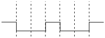
Solution
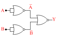
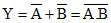
Behaving like NAND gate.
∴ A = 1001100
B = 1010101
A . B = 1000100
∴ Y =
 = 0111011
Create a free account to view solution
View Solution FreeMore Semiconductor Questions
For a transistor amplifier in common emitter configuration having load impedance of 1 kΩ (hfe = 50 and hoe = 25) th...The diagram of a logic circuit is given below. The output of the circuit is represented by : -...In an n-p-n transistor (in common emitter mode) 1010 electrons enter the emitter in 10-6 sec. Only 2% of the electrons a...An ideal Zener diode with breakdown voltage of -3 V is reverse biased with a negative input voltage $V_{i} = - 5\text{ }...In the circuit below, A and B represent two inputs and C represents the output. The circuit represents...