Current Electricity and Electrical InstrumentMedium
Question
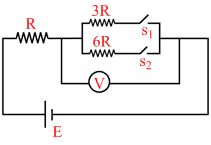
In the circuit shown in figure reading of voltmeter is V1 when only S1 is closed, reading of voltmeter is V2 when only S2 is closed and reading of voltmeter is V3 when both S1 and S2 are closed. Then
Options
A.V3 > V2 > V1
B.V2 > V1 > V3
C.V3 > V1 > V2
D.V1 > V2 > V3
Solution
Case - I
For ideal voltmeter
V1 = . 3R
 E = 0.75 E
Case - II V2 = . 6R =
 E = 0.857 E
Case - III V3 = .2R =
 E = 0.666 E
For ideal voltmeter
V1 =
. 3R E = 0.75 ECase - II V2 =
. 6R = E = 0.857 ECase - III V3 =
.2R = E = 0.666 ECreate a free account to view solution
View Solution FreeTopic: Current Electricity and Electrical Instrument·Practice all Current Electricity and Electrical Instrument questions
More Current Electricity and Electrical Instrument Questions
When a voltmeter and an ammeter are connected respectively across the terminals of a cell, measures 5 V and 10 A. Now on...In the fig. the potentiometer wire AB of length L & resistance 9 r is joined to the cell D of e.m.f. ε & internal r...In the adjacent circuit, AB is a potentiometer wires of length 40 cm no resistance per unit length 50Ω /m. As shown...A galvanometer coil has a resistance 90W and full scale deflection correct 10mA. A 910W resistance is connected in serie...Which of the following statement is wrong : -...