Current Electricity and Electrical InstrumentEasy
Question
In the circuits (a) and (b) switches S1 and S2 are closed at t = 0 and are kept closed for a long time. The
variation of currents in the two circuits for t ≥ 0 are roughly shown by (figures are schematic and not drawn to scale :
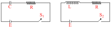
variation of currents in the two circuits for t ≥ 0 are roughly shown by (figures are schematic and not drawn to scale :
Options
A.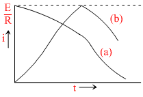
B.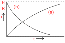
C.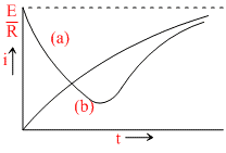
D.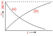
Solution
For capacitor circuit i = i0e-t/RC
For inductor circuit i = i0
For inductor circuit i = i0
Create a free account to view solution
View Solution FreeTopic: Current Electricity and Electrical Instrument·Practice all Current Electricity and Electrical Instrument questions
More Current Electricity and Electrical Instrument Questions
The resistance of hot tungsten filament is about 10 times the cold resistance. What will be the resistance of 100 W and ...Two identical galvanometers are taken, one is two be converted into an ammeter and other into a milliammeter, Shunt of m...Four identical bulbs each rated 100 watt, 220 volts are connected across a battery as shown. The total electric power co...The current i in the circuit (see figure) is :...We shall observe in the galvanometer:...