SemiconductorMedium
Question
The following figure shows a logic gate circuit with inputs A and B and the output Y. The voltage waveform of A, B and Y are as given.
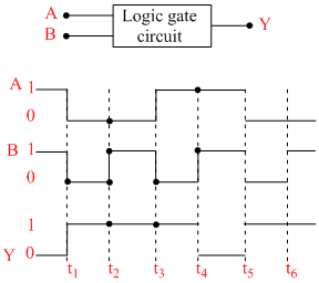
The logic gate is
The logic gate is
Options
A.NOR gate
B.OR gate
C.AND gate
D.NAND gate
Solution
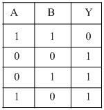
It is clear from given logic circuit, that out put Y is low when both the inputs are high, otherwise it is high. Thus logic circuit is NAND gate.
Create a free account to view solution
View Solution FreeMore Semiconductor Questions
If the lattice constant of this semiconductor is decreased, then which of the following is correct?...Which on of the following is true about the p-type and n-type semi -conductor ?...The value of barrier potential of p-n junction or n-p junction in Ge is : -...At K temperature a p-type semiconductor...At abosolute zero temperature, pure germanium and silicon are : -...